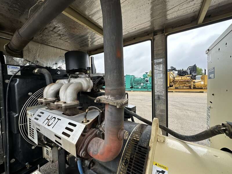
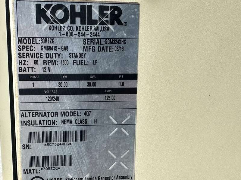
Service parts for the 30REZG
Grouped by system, with how many of each the parts manual calls for.
Air intake
1 requiredOil system
1 requiredBelts
1 requiredIgnition
1 requiredPrices captured from merchant listings; some links are affiliate links. Confirm against your serial number before ordering.
Specifications
| Fuel | Natural Gas / LP |
|---|---|
| Frequency | 60.0 Hz |
| Standby power | 30 kW |
| Standby kVA | 38 |
| Prime power | 27 kW |
| Controller | Decision-Maker 3000, Decision-Maker 3500 |
| Oil capacity | 4.7 L |
| Alternator | PMG |
| Voltage options | 480 V |
| Phase | 3 |
| Max ambient | 50 °C |
| Sound level | 74.0 dBA @ 23 m |
Engine
| Oil capacity | 4.7 L |
|---|---|
| Coolant capacity | 14.9 L |
| Displacement | 3.0 L |
| Aspiration | Natural Aspiration |
| Rated speed | 1 rpm |
Maintenance & consumables
for the General Motors 3.0L| Item | Spec | Capacity | Part # | Interval | |
|---|---|---|---|---|---|
| Air filter | Element, air cleaner | 253107 | Amazon $43.25 eBay $69.00 | ||
| Fuel filter | — | ||||
| Oil filter | GM16703 | Amazon $9.06 eBay $58.00 | |||
| Battery | — | ||||
| Belt | Belt, alternator | GM39428 | Amazon eBay $15.00 | ||
| Coolant | — | ||||
| Oil | — | ||||
| Spark plug | Spark plug | GM38998 | Amazon eBay |
Service intervals
2| Item | Action | Hours | Months | Notes |
|---|---|---|---|---|
| Paralleling box | Inspect | 12 mo | Annually by a Kohler authorized distributor/dealer, or when wear, damage, deterioration, or malfunction is evident or suspected. | |
| Paralleling box internal components | Inspect | 1 mo | Monthly or when a condition noticed during external inspection may have affected internal components; enclosure cover must be removed by trained personnel. |
Extracted from the manufacturer documentation linked to this model. Values are copied as printed; confirm against your unit's manual and serial number.
Service specifications
36| Type | Item | Value | Unit | Condition |
|---|---|---|---|---|
| Other | 10 in. weld flange bolt circle diameter B | 361.95 | mm (14.25 in.) | |
| Other | 10 in. weld flange outside diameter C | 406.4 | mm (16.0 in.) | |
| Other | 10 in. weld flange quantity of bolts / bolt hole diameter D | 12, 25.40 | mm (1.00 in.) | |
| Other | 12 in. weld flange bolt circle diameter B | 431.80 | mm (17.00 in.) | |
| Other | 12 in. weld flange outside diameter C | 482.6 | mm (19.0 in.) | |
| Other | 12 in. weld flange quantity of bolts / bolt hole diameter D | 12, 25.40 | mm (1.00 in.) | |
| Other | 14 in. weld flange bolt circle diameter B | 476.25 | mm (18.75 in.) | |
| Other | 14 in. weld flange outside diameter C | 533.4 | mm (21.0 in.) | |
| Other | 14 in. weld flange quantity of bolts / bolt hole diameter D | 12, 28.58 | mm (1.13 in.) | |
| Other | 16 in. weld flange bolt circle diameter B | 539.75 | mm (21.25 in.) | |
| Other | 16 in. weld flange outside diameter C | 596.9 | mm (23.5 in.) | |
| Other | 16 in. weld flange quantity of bolts / bolt hole diameter D | 16, 28.58 | mm (1.13 in.) | |
| Other | 18 in. weld flange bolt circle diameter B | 577.85 | mm (22.75 in.) | |
| Other | 18 in. weld flange outside diameter C | 635.0 | mm (25.0 in.) | |
| Other | 18 in. weld flange quantity of bolts / bolt hole diameter D | 16, 31.75 | mm (1.25 in.) | |
| Other | 20 in. weld flange bolt circle diameter B | 635.00 | mm (25.00 in.) | |
| Other | 20 in. weld flange outside diameter C | 698.5 | mm (27.5 in.) | |
| Other | 20 in. weld flange quantity of bolts / bolt hole diameter D | 20, 31.75 | mm (1.25 in.) | |
| Other | 5 in. weld flange bolt circle diameter B | 215.90 | mm (8.50 in.) | |
| Other | 5 in. weld flange outside diameter C | 241.30 | mm (9.50 in.) | |
| Other | 5 in. weld flange quantity of bolts / bolt hole diameter D | 8, 22.23 | mm (0.88 in.) | |
| Other | 6 in. weld flange bolt circle diameter B | 254.0 | mm (10.0 in.) | |
| Other | 6 in. weld flange outside diameter C | 279.4 | mm (11.0 in.) | |
| Other | 6 in. weld flange quantity of bolts / bolt hole diameter D | 8, 22.23 | mm (0.88 in.) | |
| Other | 8 in. weld flange bolt circle diameter B | 298.45 | mm (11.75 in.) | |
| Other | 8 in. weld flange outside diameter C | 342.9 | mm (13.5 in.) | |
| Other | 8 in. weld flange quantity of bolts / bolt hole diameter D | 8, 22.23 | mm (0.88 in.) | |
| Other | Engine speed adjustment | 50 | default setting; settings between 40 and 60 acceptable; 52 increases speed by 2 RPM, 49 decreases by 1 RPM | |
| Other | Generator to bus phase angle | -10 to 10 | degrees | verify with contactor closed |
| Other | Reactive droop | 1 | % | default setting; range 0.5 - 2% |
| Other | Weld flange angle A (10, 12, 14 in. nominal pipe size) | 30 | deg. | |
| Other | Weld flange angle A (16, 18, 20 in. nominal pipe size) | 22.5 | deg. | |
| Other | Weld flange angle A (5, 6, 8 in. nominal pipe size) | 45 | deg. | |
| Torque | PGEN terminal block connections | 0.5 | Nm | |
| Torque | PGEN terminal block connections | 4.4 | in. lbs. | |
| Voltage | Controller measurement accuracy | 2 | % | without calibration; requires a calibrated multimeter for calibration |
Extracted from the manufacturer documentation linked to this model. Values are copied as printed; confirm against your unit's manual and serial number.
Procedures
12Calibration adjustment
⚠ Copying personality profiles from one controller to another can overwrite calibration coefficients and requires re-calibration.
Tools: Calibrated multimeter with recent calibration verification
- Use a calibrated multimeter to measure the generator voltage and enter the correct value in the CONTROLLER CONFIG -> CALIBRATION screen.
- Use a calibrated multimeter to measure the bus voltage and enter the correct value in the CONTROLLER CONFIG -> CALIBRATION screen.
Verify Generator Operation diagnostic
⚠ Generators must all operate at the same frequency, voltage, and phase connection in order to parallel.
Tools: SiteTech software
- Ensure the load is not connected or is drawing less power than a single generator can provide.
- Navigate to CONTROLLER CONFIG -> COMMUNICATION SETUP and verify PGEN Nodes Online indicates the correct number of nodes.
- Verify alternator connection (voltage selector switch position), system voltage, and voltage regulator target on each generator.
- Start a single generator by pressing the Run button; the paralleling box contactor should close and the Generator Connected to Bus indicator should light.
- Verify bus and generator voltages match and generator to bus phase angle is between -10 and 10 degrees.
- Verify the load bus is energized and available at the load.
- Stop the generator by pressing the OFF button; the contactor should open.
- Repeat for each generator in the paralleling system.
Verify Paralleling and Load Sharing diagnostic
Tools: Load bank (optional)
- Place all generators in automatic mode by pressing the Auto button; verify the red shutdown indicator is not illuminated.
- Provide a local start request by holding AUTO, pressing RUN, releasing RUN, then releasing AUTO.
- Verify all generators start, one generator closes its contactor, and the others synchronize and close their contactors.
- Verify that the % of rated power of the generators matches, showing the generators are sharing load equally.
- If a load bank is available, test the system under load.
Control Harness Connections installation
⚠ The control harness connections for GEN 1 and GEN 2 must correspond to the source camlock cable connections.
- Connect the control harness from the generator set connected to the GEN 1 camlock connectors to GEN 1 CONTROL.
- Connect the control harness from the generator set connected to the GEN 2 camlock connectors to GEN 2 CONTROL.
- When not used, store the control harnesses on the storage rack inside the enclosure.
Grounding installation
⚠ Grounding electrical equipment: hazardous voltage can cause severe injury or death. Turn off the main circuit breakers of all power sources before servicing.
- Connect the ground lug on the paralleling box to earth ground according to applicable state and local codes.
- Follow NEC guidelines for grounding electrical equipment.
- The neutral is bonded to ground inside the paralleling box; if required, remove the bonding bus to disconnect neutral from ground.
Load Connections installation
⚠ Multiple power sources can automatically energize the distribution bus. Disconnect all power sources before connecting to the distribution bus.
- Remove the camlock security guard from one row of connectors for each generator and store the guard.
- Connect the load side ground (green) camlock cables to the distribution bus and then to the paralleling box.
- Connect the load side neutral (white) camlock cables to the distribution bus and then to the paralleling box.
- Connect the load side L1 (black), L2 (red), and L3 (blue) camlock cables to the distribution bus and then to the paralleling box.
Multiple Paralleling Boxes (PGEN Connections) installation
- Connect one or two generators to each paralleling box.
- Use Belden cable #9841 (or equivalent) shielded twisted-pair communication cable to connect the PGEN terminal blocks on the paralleling boxes.
- Tighten the connections to 0.5 Nm (4.4 in. lbs.).
Paralleling System Setup installation
⚠ Generator management must be disabled manually at each generator set controller.
Tools: Personal computer with SiteTech software
- Check that the voltage selector switch and/or alternator wiring matches the building voltage configuration for all generator sets.
- Set the digital output to Contactor (SiteTech Programmable Digital Output 116).
- Set reactive droop to 0.5-2% (default 1%), using the same reactive droop setting on all generators.
- Set the target voltage on all paralleled generators to the same value.
- Set engine speed adjustment to 50 on all generators (default 50; range 40-60).
- Verify metering; if voltage is incorrect, use the calibration procedure.
- Set Sync Mode in AUTO to ACTIVE and Sync Mode in Run to CHECK on all generators.
- Set Generator Management Enabled to OFF at each generator unless generator management is requested.
- Set up load management (load shed priorities) for non-critical loads.
- Stop all generators by pressing the OFF button on each controller.
Source Connections installation
⚠ Hazardous voltage. This equipment must be installed and serviced by qualified electrical personnel. Do not connect or disconnect cables under load.
- Remove the camlock security guard from one row of connectors for each generator and store the guard.
- Generator 2 connects to the upper set of camlocks; generator 1 connects to the lower set.
- Connect the source side ground (green) camlock cables to the paralleling box first and then to each generator.
- Connect the source side neutral (white) camlock cables to the paralleling box first and then to each generator.
- Connect the source side L1 (black), L2 (red), and L3 (blue) camlock cables to the paralleling box first and then to each generator.
Storage Procedure maintenance
⚠ Do not open the electrical compartment on the opposite side of the enclosure; that compartment should be opened only by Kohler authorized distributors or dealers.
- Store control harnesses on the storage rack inside the box when not in use.
- Lock the cabinet door with the key provided and store the key in a secure location.
- Use the guards to cover the camlock connectors.
- Attach padlocks to the electrical panel cover and the camlock guards to prevent unauthorized access.
Disable the Generator Sets operation
⚠ Accidental starting can cause severe injury or death. Remove the negative (-) lead first when disconnecting the battery; reconnect it last.
- Press the generator set master control OFF/RESET button.
- Disconnect the power to the battery charger, if equipped.
- Disconnect the generator set engine starting battery(ies), negative (-) lead first.
Re-enable the Generator Sets operation
⚠ Reconnect the battery correctly, positive to positive and negative to negative, to avoid electrical shock and damage.
- Check that the generator set is OFF.
- Reconnect the generator set engine starting battery, negative (-) lead last.
- Reconnect power to the battery charger, if equipped.
Extracted from the manufacturer documentation linked to this model. Values are copied as printed; confirm against your unit's manual and serial number.
Voltage reconnection
| Voltage | Phase | Connection | Leads | Notes |
|---|---|---|---|---|
| 12-Lead | Alternator Reconnections diagram ADV-5875B-M (page 16) | |||
| 4-Lead | Alternator Reconnections diagram ADV-5875A-M (page 15) |
Extracted from the manufacturer documentation linked to this model. Values are copied as printed; confirm against your unit's manual and serial number.
Common questions
What is the power rating of the Kohler 30REZG?
The Kohler 30REZG is rated 30 kW standby (38.0 kVA).
What engine is in the Kohler 30REZG?
The Kohler 30REZG is powered by the General Motors 3.0L engine.
What fuel does the Kohler 30REZG use?
The Kohler 30REZG runs on Natural Gas / LP.
How much oil does the Kohler 30REZG take?
The General Motors 3.0L engine in the Kohler 30REZG has an oil capacity of 4.7 liters.
What alternator comes on the Kohler 30REZG?
The Kohler 30REZG uses a PMG alternator.
Which oil filter part number does the Kohler 30REZG take?
The Kohler 30REZG uses oil filter part number GM16703.
Which air filter part number does the Kohler 30REZG take?
The Kohler 30REZG uses air filter part number 253107.
Troubleshooting
2Symptoms & remedies
| Symptom | Cause | Remedy |
|---|---|---|
| Low Coolant Temperature (LCT) fault alarms occur even when a block heater is installed and properly functioning. | The LCT sender was installed in the incorrect location on the unit. In this case, the sender was installed in a tee fitting on the return line from the engine block to the block heater. The correct LCT location is in the thermostat housing. | |
| The LCT sender/switch at the tee of the return line between the engine block and block heater has two terminals, indicating it is an incorrect sender/switch. | Order LCT sender GM39458. Go to step 1.3. |
Fault codes and symptom→remedy steps extracted from this model’s service/owner documentation; verify against the official manual before servicing.
Parts
18| Part # | Description | Qty | System | |
|---|---|---|---|---|
| 1259369GT | Manifolds | Manifold | Amazon eBay | |
| 253107 | Element, Air Cleaner | 1 | Air filter | Amazon $43.25 eBay $69.00 |
| 4024TF281 | Fan Belt | 1 | Belt | Amazon eBay |
| GM16132 | Belt, fan standard | 1 | Belt | Amazon eBay $86.00 |
| GM16531 | Spark plug | 1 | Oil filter | Amazon eBay $8.08 |
| GM16703 | Filter, oil | 1 | Oil filter | Amazon $9.06 eBay $58.00 |
| GM19726 | Thermostat | 1 | Spark plug | Amazon eBay |
| GM22171 | Spark plug | 8 | Oil filter | Amazon eBay |
| GM34935 | Fuel Filter | 1 | Fuel filter | Amazon eBay $37.99 |
| GM38998 | Spark plug | 1 | Oil filter | Amazon eBay |
| GM39428 | Belt, alternator | 1 | Oil filter | Amazon eBay $15.00 |
| GM39458 | LCT Sender | 1 | Sensor | Amazon eBay |
| GM62309 | Element, air cleaner | 1 | Oil filter | Amazon eBay $91.00 |
| GM63750 | Oil Filter | 1 | Oil filter | Amazon eBay |
| GM63809 | Fuel Filter (primary) | 1 | Fuel filter | Amazon eBay |
| GM65427 | Belt, alternator | 1 | Oil filter | Amazon eBay $79.00 |
| GM74021-C | Pipe sealant | Fluid | Amazon eBay | |
| GM79585--S | Thermostat | 1 | Thermostat | Amazon eBay eBay |
Service, wear & replacement parts referenced for this model and its engine — confirm the exact part for your serial number. See the full parts catalog to search and cross-reference.
Fuel consumption
| Rating | Load | L/h | gal/h |
|---|---|---|---|
| Prime | 25% | 138.0 | 36.46 |
| Prime | 50% | 192.0 | 50.72 |
| Prime | 75% | 251.0 | 66.31 |
| Prime | 100% | 314.0 | 82.95 |
| Prime | 110% | 345.0 | 91.14 |
| Standby | 25% | 144.0 | 38.04 |
| Standby | 50% | 204.0 | 53.89 |
| Standby | 75% | 271.0 | 71.59 |
| Standby | 100% | 345.0 | 91.14 |