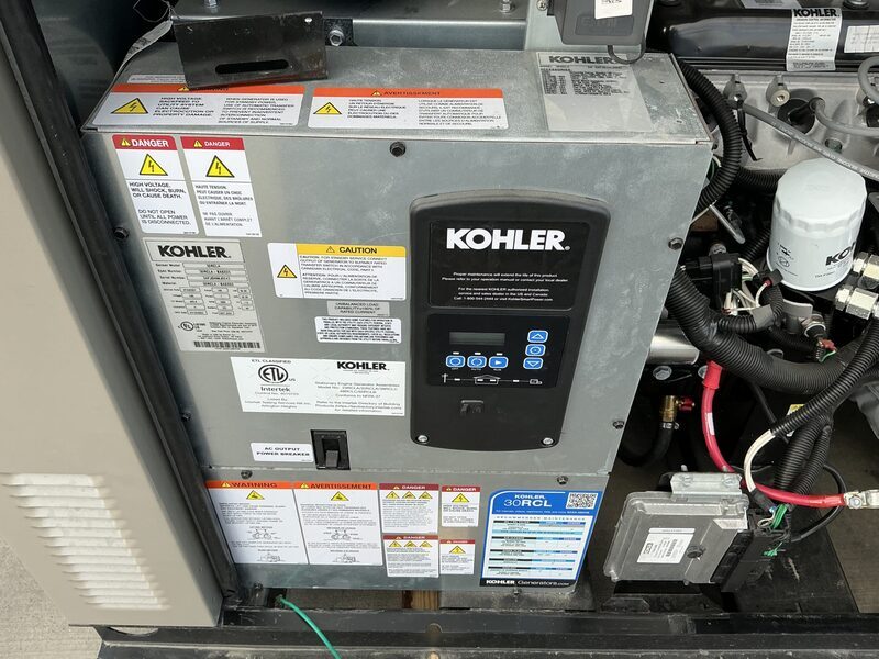
Service parts for the 30RCL
Grouped by system, with how many of each the parts manual calls for.
Ignition
1 requiredPrices captured from merchant listings; some links are affiliate links. Confirm against your serial number before ordering.
Specifications
| Fuel | Natural Gas/LPG |
|---|---|
| Frequency | 60.0 Hz |
| Standby power | 30 kW |
| Standby kVA | 30 |
| Emissions | EPA certified |
| Controller | RDC2 |
| Oil capacity | 4.2 L |
| Alternator | 4D8.3 (Class H insulation) |
| Voltage options | 120/240 V, 120/208 V, 127/220 V, 277/480 V |
| Phase | 1 |
| Rated current | 125 A |
| Power factor | 1.0 |
| Battery group | 24 |
| Battery cranking | 630 CCA |
| Battery voltage | 12 V |
| Battery quantity | 1 |
| Coolant capacity | 13.2 L |
| Max ambient | 45 °C |
| Dimensions (L×W×H) | 1880×836×1169 mm |
| Dry weight | 599 kg |
| Wet weight | 599 kg |
| Sound level | 61.0 dBA @ 7 m |
Engine
| Oil capacity | 4.2 L |
|---|---|
| Coolant capacity | 13.2 L |
| Displacement | 2.2 L |
| Aspiration | Naturally aspirated (KG2204); Turbocharged (KG2204T) |
| Rated speed | 1800 rpm |
Maintenance & consumables
for the Kohler KG2204/KG2204T| Item | Spec | Capacity | Part # | Interval | |
|---|---|---|---|---|---|
| Air filter | — | 400 hr | |||
| Oil filter | Cartridge | ×1 | — | 120 hr | |
| Battery | BCI group 24 size 12-volt minimum 630 CCA at 0_F | — | 120 hr | ||
| Belt | Deflection new 5-7mm, used 7-8mm at 98N test pressure | — | 120 hr | ||
| Coolant | 50% ethylene glycol-based long-life coolant | 13.2 L | — | 500 hr | |
| Oil | 4.2 L | — | 120 hr | ||
| Spark plug | KG2204: GM92785, M14 x 1.25 thread; KG2204T: GM100158 | GM92785 | 500 hr | Amazon eBay |
Service intervals
25| Item | Action | Hours | Months | Notes |
|---|---|---|---|---|
| Air cleaner element | Clean | 20 hr | 3 mo | Replace at 3 years or 400 hours |
| Bolts and nuts for tightness | Check | 20 hr | 3 mo | Quarterly or 20 hours |
| Battery cables | Clean | 120 hr | 12 mo | |
| Battery charge | Check | 120 hr | 12 mo | |
| Battery fluid level | Check | 120 hr | 12 mo | |
| Battery for cracks and corrosion | Check | 120 hr | 12 mo | |
| Belts and belt tension | Check | 120 hr | 12 mo | See engine O/M |
| Engine oil and filter | Change | 120 hr | 12 mo | |
| Fuel regulator pressure | Check | 120 hr | 12 mo | |
| Radiator exterior | Check | 120 hr | 12 mo | |
| Brushes and collector ring | Other | 300 hr | 12 mo | Authorized distributor/dealer only |
| Air induction for leaks | Check | 500 hr | 36 mo | |
| Engine coolant | Change | 500 hr | 36 mo | Long-life coolant: 5000 hours or 5 years |
| Hoses, condition | Check | 500 hr | 36 mo | Replace as necessary |
| Intake manifold for vacuum leaks | Check | 500 hr | 36 mo | |
| Secondary ignition coil wires | Check | 500 hr | 36 mo | Replace as necessary |
| Spark plug wires for cuts, abrasions, or hardening | Check | 500 hr | 36 mo | Replace as necessary |
| Spark plugs | Change | 500 hr | 36 mo | |
| Exhaust manifold for leaks | Check | 2000 hr | 60 mo | Replace as necessary |
| Exhaust piping for leaks | Check | 2000 hr | 60 mo | |
| Fuel shutoff valve operation | Check | 2000 hr | 60 mo | |
| HEGO (oxygen) sensor connections and wires | Check | 2000 hr | 60 mo | See engine O/M |
| Fuel lines and connections | Check | 3 mo | Quarterly | |
| Vacuum lines and fittings | Inspect | 60 mo | 5 years | |
| Wiring for cuts, abrasions, or corrosion | Inspect | 60 mo | 5 years |
Extracted from the manufacturer documentation linked to this model. Values are copied as printed; confirm against your unit's manual and serial number.
Service specifications
18| Type | Item | Value | Unit | Condition |
|---|---|---|---|---|
| Gap | Spark plug gap | 0.51 | mm (0.02 in.) | |
| Gap | Spark plug gap | 0.7--0.8 | mm (0.028--0.030 in.) | |
| Gap | Spark plug gap | 0.7-0.8 | mm (0.028-0.030 in.) | |
| Gap | Spark plug gap | 0.76 | mm (0.03 in.) | |
| Gap | Spark plug gap | 0.8--0.9 | mm (0.03--0.04 in.) | |
| Gap | Spark plug gap | 0.89 | mm (0.035 in.) | |
| Gap | Spark plug gap | 0.9--1.0 | mm (0.036--0.04 in.) | |
| Gap | Spark plug gap | 0.9-1.0 | mm (0.036-0.040 in.) | |
| Pressure | Radiator pressure cap rating | 97 | kPa (14 psi) | |
| Torque | Oil filter | 25 | Nm (18.4 ft. lbs.) | after hand-tight plus 3/4 turn |
| Torque | Spark plug | 18 | Nm (13.3 ft. lbs.) | plus additional 1/4 turn |
| Torque | Spark plug | 25 | Nm (18.4 ft. lbs.) | plus additional 1/4 turn |
| Torque | Spark plug torque | 15 | Nm (11 ft. lb.) | |
| Torque | Spark plug torque | 18 | Nm (13.3 ft. lb.) | |
| Torque | Spark plug torque | 24.4--29.8 | Nm (18--22 ft. lb.) | |
| Torque | Spark plug torque | 25 | Nm (18 ft. lb.) | |
| Voltage | Undervoltage dropout (ATS source availability) | 90 | % of pickup | |
| Voltage | Undervoltage pickup (ATS source availability) | 90 | % of nominal |
Extracted from the manufacturer documentation linked to this model. Values are copied as printed; confirm against your unit's manual and serial number.
Recommended fluids
| Fluid | Grade | Standard | Ambient | Capacity | Notes |
|---|---|---|---|---|---|
| Coolant | 50% ethylene glycol-based long-life coolant / 50% clean, softened water | above -37°C | 13.2 L (3.5 gal.) | 13.7 L (3.6 gal.) with block heater; freeze protection to -37C (-34F), overheat protection to 149C (300F) | |
| Engine oil | SAE 5W-30 (cold environments); 10W-30 (hot environments, never below 0C/32F) | API Starburst certification, service class SJ or higher (gasoline engines) | 4.2 L (4.4 qt.) | CC/CD classification oils not acceptable |
Extracted from the manufacturer documentation linked to this model. Values are copied as printed; confirm against your unit's manual and serial number.
Fault codes
44| Code | Name | Meaning | Severity | Action |
|---|---|---|---|---|
| AC Sens Loss | AC Sensing Lost | AC sensing lost in Auto mode; warning after 1 sec if no output after crank disconnect, shutdown after 3 sec if voltage was present then lost | Warning | Contact an authorized distributor/dealer for service |
| ATS ComError | ATS Communication Error | RXT interface connection is lost | Warning | Check communication wiring between transfer switch interface board and generator set |
| ATS PhaseRot | ATS Phase Rotation Mismatch | Transfer switch phase rotation does not match; ATS will not transfer | Warning | Correct the ATS connection per installation manual, wiring diagrams, and labels |
| Accy PwrOver | Accessory Power Overload | Over current fault (short circuit) on the accessory controller power output | Warning | Contact an authorized distributor/dealer for service |
| Aux Input | Auxiliary Input | An optional customer-connected input is closed (digital input from optional PIM) | Shutdown | Check customer-supplied equipment |
| Battery CrLo | Critically Low Battery Voltage | Battery voltage falls below 11V for more than 10 seconds; inhibited during crank | Warning | Check battery rating/condition and charger operation; charge or replace battery |
| Battery High | High Battery Voltage | Battery voltage rises above 133% (16V) of the battery voltage setting for more than 10 seconds | Warning | Check battery rating/condition and charger operation |
| Battery Low | Low Battery Voltage | Battery voltage falls below the battery voltage setting (typically 12.5V) for more than 90 seconds when engine is not running | Warning | Check battery rating/condition and charger operation; charge or replace battery |
| Chk DateTime | Verify Date Time Setting | The time and date have not been set on the generator controller | Warning | Enter the date and time using the RDC2 controller |
| CoolTemp Vhi | Ect Higher Than Expected 2 | Coolant temperature is extremely high | Shutdown | Check coolant level; check radiator/fans for obstruction; contact dealer with fault code |
| CoolTempHigh | Ect Higher Than Expected 1 | Coolant temperature is too high | Warning | Check coolant level; check radiator/fans for obstruction; contact dealer with fault code |
| Coolant Lvl Low | Low Coolant Level Shutdown | The coolant level switch input has been activated | Shutdown | Check coolant level; check radiator hoses for leaks; contact dealer |
| CoolntTemp 0 | Coolant Temp 0 Shutdown | ECM reported coolant temperature sensor problem: 0 = high temperature | Shutdown | Check coolant level and radiator/fans; contact dealer with fault code |
| CoolntTemp 3 | Coolant Temp 3 Shutdown | ECM reported coolant temperature sensor problem: 3 = high voltage | Shutdown | Contact an authorized distributor/dealer for service and provide the fault code |
| CoolntTemp 4 | Coolant Temp 4 Shutdown | ECM reported coolant temperature sensor problem: 4 = low voltage | Shutdown | Contact an authorized distributor/dealer for service and provide the fault code |
| CoolntTemp 5 | Coolant Temp 5 Shutdown | ECM reported coolant temperature sensor problem: 5 = open circuit | Shutdown | Contact an authorized distributor/dealer for service and provide the fault code |
| Crank Lost | Crank Signal Lost | Crankshaft Position Sensor (CPS) timeout error occurred | Warning | Contact an authorized distributor/dealer for service and provide the fault code |
| ECM warnings | ECM warnings (any warning with ECM in the fault name) | Group of faults that originate from the engine ECM and contain ECM in the fault name | Warning | Contact an authorized distributor/dealer for service and provide the fault code |
| Emerg Stop | Emergency Stop Shutdown | The emergency stop switch has been activated, or there has been an open circuit in the wiring | Shutdown | Contact an authorized distributor/dealer for service |
| Eng Speed High | High Engine Speed | Engine speed exceeds 115% of normal running speed for more than 0.3 seconds | Shutdown | Contact an authorized distributor/dealer for service |
| Eng Speed Low | Low Engine Speed | Engine speed drops below 85% of normal running speed for more than 3 seconds | Shutdown | Reduce the load; contact an authorized distributor/dealer for service |
| Exer Not Sch | ATS Exercise Not Scheduled | No exercise has been scheduled on the RDC2 controller | Warning | Set the exerciser per Section 2.5 |
| Frequency High | High Frequency | Governed frequency exceeds 110% of system frequency setpoint for more than 10 seconds (10 sec inhibit after start) | Shutdown | Contact an authorized distributor/dealer for service |
| Frequency Low | Low Frequency | Governed frequency falls below 90% of system frequency setting for more than 10 seconds, or 1 Hz below setting for more than 60 seconds | Shutdown | Reduce the load and restart; contact dealer |
| Genset S/N Unaval | Unavailable Genset Serial Number | Generator set serial number is unavailable | Warning | Contact an authorized distributor/dealer for service |
| Ground Fault | Ground Fault Warning | The digital input for Ground Fault Warning is active (low); PIM required | Warning | Check customer equipment connected to the PIM |
| IAT High 1 | Iat Higher Than Expected 1 | Engine manifold air temperature is too high | Warning | Contact an authorized distributor/dealer for service and provide the fault code |
| IAT Volt Lo | Iat Low Voltage | ECM reported an Engine Air Temperature/Manifold Absolute Pressure Sensor (TMAP) error | Warning | Contact an authorized distributor/dealer for service and provide the fault code |
| Lo Crank Vlt | Low Cranking Voltage | Battery voltage falls below 60% of system battery voltage for more than 6 seconds while the starter is engaged | Warning | Charge or replace the battery |
| Locked Rotor | Locked Rotor | No engine rotation is sensed during cranking; shuts down 3 seconds after fault detected | Shutdown | Check battery, connections, and for obstruction of alternator or engine; contact dealer |
| MainPwrOverL | Main Power Overload | Over current fault on the controller power output (short circuit) | Shutdown | Check for shorted run relay; check wiring for short circuits; contact dealer |
| Maint Req'd | Maintenance Required Warning | Engine maintenance is due | Warning | Check the maintenance schedule in the operation manual |
| Not in Auto | Not In Auto | The generator set is not in Automatic (standby) mode; remote start/stop commands will be ignored | Warning | Press AUTO to place the generator set in Automatic mode |
| Oil Pres Low | Low Oil Pressure | The engine ECM indicates low oil pressure | Shutdown | Check for leaks in the lubrication system; check oil level; check oil pressure switch and wiring |
| Over Crank | Over Crank | Three unsuccessful starting attempts | Shutdown | Check fuel supply, spark plug, battery, and connections; contact dealer |
| PrimLoopOpn | Primary Loop Open | Ignition coil 1 voltage is below normal or there is an open circuit | Warning | Check the battery voltage; contact dealer with fault code |
| PrimLoopSht | Primary Loop Shorted | Ignition coil 1 voltage is abnormal | Warning | Check the battery voltage; contact dealer with fault code |
| Spd Sens Flt | Speed Sensor Fault | Engine speed sensor has failed or engine stalled; ECM no longer reporting valid speed | Shutdown | Contact an authorized distributor/dealer for service |
| Volts L1-L2 High | High Generator Voltage L1-L2 | Output voltage exceeds 120% of system nominal voltage for more than 2 seconds | Shutdown | Contact an authorized distributor/dealer for service |
| Volts L1-L2 Low | Low Generator Voltage L1-L2 | Output voltage falls below 80% of nominal system voltage for more than 10 seconds | Shutdown | Reduce the load and restart; contact dealer |
| Volts L2-L3 High | High Generator Voltage L2-L3 | Output voltage exceeds 120% of system nominal voltage for more than 2 seconds | Shutdown | Contact an authorized distributor/dealer for service |
| Volts L2-L3 Low | Low Generator Voltage L2-L3 | Output voltage falls below 80% of nominal system voltage for more than 10 seconds | Shutdown | Reduce the load and restart; contact dealer |
| Volts L3-L1 High | High Generator Voltage L3-L1 | Output voltage exceeds 120% of system nominal voltage for more than 2 seconds | Shutdown | Contact an authorized distributor/dealer for service |
| Volts L3-L1 Low | Low Generator Voltage L3-L1 | Output voltage falls below 80% of nominal system voltage for more than 10 seconds | Shutdown | Reduce the load and restart; contact dealer |
Extracted from the manufacturer documentation linked to this model. Values are copied as printed; confirm against your unit's manual and serial number.
Procedures
12RDC2 Voltage Calibration Using SiteTech adjustment
Tools: digital voltmeter, personal computer, SiteTech software
- Connect PC to controller via USB
- With generator off, connect multimeter across L1/L2 (AC volts)
- Start generator set
- Compare voltmeter reading to controller display
- Calculate new Genset Calibration Factor Voltage using (Vmeter / Vcontrol) x Fold = Fnew
- Enter new value into SiteTech and click Apply Changes
- Verify voltmeter matches controller display
- Repeat for L2-L3 and L3-L1 if three-phase
- Press OFF to stop generator set
RDC2 Voltage Calibration Using the Controller Keypad adjustment
Tools: digital voltmeter
- With generator off, connect digital multimeter across L1 and L2, set to AC volts
- Start generator set with RUN button
- Navigate to Generator Metering menu, press Select; Volts L1-L2 displayed
- Press Select; voltage number flashes
- Use up/down arrows to match voltmeter reading
- Press Select to confirm
- Step to Return screen
- Press OFF to stop generator set
VSC Current (Load) Calibration Using the Controller Keypad adjustment
Tools: clamp-on DC current probe or DC current meter
- Connect DC current probe/clamp meter to measure generator current
- Start generator with RUN button
- Adjust system voltage to obtain rated current output with battery bank attached (or use load bank)
- Trip output breaker
- Navigate to Generator Metering menu, select Generator Load
- Press and hold Select for No-Load Calibration; verify breaker open, confirm Yes
- Close output breaker; verify rated output current, confirm Yes
- Verify displayed load is correct; recalibrate if necessary
- Press OFF to stop generator set
Resetting the Controller after a Fault Shutdown diagnostic
⚠ Always identify and correct the cause of a fault shutdown before resetting
- Press the Select button to go to the Overview menu
- Press Select again to display the active fault
- Press Select; Confirm Clear Fault: NO is displayed
- Press the Up arrow button; Confirm Clear Fault: YES is displayed
- Press Select to enter YES and clear the fault
- Press Select to return to the Overview menu
- Press AUTO to put the generator set into automatic mode
Installation Guidelines installation
⚠ Minimum 8 feet clearance from exhaust end
⚠ Verify state and local codes for installation distance requirements
- Position exhaust aimed away from or parallel to structure
- Do not direct exhaust at play areas or gathering spaces
- Maintain minimum 5 feet distance from windows, vents, doors or openings
- Install minimum 18 inches from structure per NFPA 37
- Close windows and doors on adjacent walls
- Keep furnace and intakes at least 10 feet from exhaust end
- Provide 4 inch thick concrete pad extending 6 inches beyond genset
- Maintain clear area with no combustibles within 8 feet of exhaust
- Keep sensitive plants and patio furniture at least 8 feet from exhaust
Air Cleaner Element and Precleaner maintenance
- Disable set: press OFF button, disconnect battery charger power, remove battery cables, negative (--) lead first.
- Loosen the cover retaining knob(s) or release the retaining clips and remove the cover.
- Remove and discard the old air cleaner element and precleaner (if equipped).
- Install the precleaner over the new air cleaner element.
- Install the paper element onto the air cleaner base, making sure it is flat and properly seated.
- Reinstall the element cover, element cover nut, and the air cleaner cover; secure with the knob(s) or clips.
- 15RES/30RES and RCL models: wipe cover and housing with a clean rag and make sure sealing surfaces fit correctly.
- Reconnect the battery cable, negative (--) lead last.
Filling Cooling System maintenance
⚠ Do not add coolant to a hot engine; cylinder block or head can crack
- Close the radiator coolant drain valve and tighten hose clamps
- Fill the radiator with 50% ethylene glycol / 50% clean softened water mixture
- Operate the engine with the radiator cap removed until the thermostat opens and upper hose is hot
- Stop the engine and allow it to cool
- Add coolant to just below the overflow tube on the filler neck
- Replace the radiator pressure cap
- Maintain the coolant overflow bottle level between Hot and Cold markings
Firmware Update Using SiteTech maintenance
⚠ Do not load RDC2.4 firmware onto a red- or green-board controller
Tools: personal computer, USB cable, SiteTech software
- Download latest firmware file (.bin) from Kohler Power Resource Center or dealer portal
- Connect controller to PC via USB cable
- Start SiteTech; program recognizes connected device
- Click Update Firmware
- Browse to and select firmware file, click Open
- Verify current/new version and file name, click Update Firmware
- Wait for 'Firmware Updated Successfully' message, click Close
Oil Change Procedure maintenance
⚠ Accidental starting can cause severe injury or death; disconnect battery, negative lead first
Tools: oil filter wrench, drain hose, funnel
- Press the OFF button on the RDC2 generator set controller
- Disconnect the power for the battery charger
- Disconnect the generator set engine starting battery, negative lead first
- Remove the housing side panel
- Remove the plug from the oil drain fitting and install a drain hose
- Open the oil drain valve on the engine
- Allow time for the engine oil to drain completely, then close the drain valve
- Replace the oil drain plug
- Remove the oil filter by rotating it counterclockwise with an oil filter wrench
- Apply a light coat of clean oil to the gasket of the new oil filter
- Thread the new filter by hand, then tighten an additional 3/4 turn (torque 25 Nm/18.4 ft. lbs.)
- Fill with 5W-30 oil per the oil capacity table
- Start the generator set and check for leaks around the oil filter
- Check oil level and add oil as necessary to the Full mark
- Reset the maintenance timer on the RDC2 controller
Oil and Oil Filter maintenance
⚠ Hot engine oil can cause severe injury or death. Avoid skin contact with hot oil.
⚠ Do not work on the generator set until it cools.
⚠ Accidental starting can cause severe injury or death. Remove the negative (--) lead first when disconnecting the battery.
Tools: Funnel, Drain tube (3/8 in. inside diameter), Catch basin / drain pan
- Disable set: press OFF button, disconnect battery charger power, remove battery cables, negative (--) lead first.
- Drain the oil while it is warm. On most models a drain plug is on the service side, opposite the starter.
- For most models remove one oil drain plug and the oil fill cap/dipstick; aim the drain tube into a catch basin.
- For most models open the valve near the oil sump and allow ample time for complete drainage.
- Close the valve and place the tube back in the clip on the bulkhead wall.
- For 8/10/12RESV(L), cover the alternator with rags near the oil drain valve and oil filter.
- For 8/10/12RESV(L), place a drain tube (3/8 in. inside diameter) onto the oil drain valve into a drain pan.
- For 8/10/12RESV(L), open the oil drain valve, remove the dipstick and oil fill cap, and drain completely.
- For 8/10/12RESV(L), close the oil drain valve and remove the oil drain tube.
- Remove the old filter, tilting it upward to prevent spilling, and wipe off the adapter/base on the engine.
- Place a new replacement filter open end up in a shallow pan; pour new oil (provided) through the threaded center hole to the bottom of threads.
- Allow a minute or two for the oil to be absorbed by the filter material.
- Apply a thin film of clean oil to the rubber gasket on the new oil filter.
- Install the new oil filter; hand tighten clockwise until the gasket contacts the adapter, then tighten an additional 3/4--1 turn.
- Fill the crankcase with new oil to the F/FULL mark on the dipstick; reinstall cap/dipstick, reconnect battery cable negative (--) lead last, test run, check for leaks, and recheck oil level.
Spark Plug Service Procedure maintenance
⚠ Accidental starting can cause severe injury or death
Tools: 13/16-in. spark plug socket with rubber insert, torque wrench, gapping tool
- Press the OFF button on the RDC2 controller
- Disconnect the power to the battery charger
- Disconnect the generator set engine starting battery, negative lead first
- Remove spark plug wires by grasping the boot and turning slightly while pulling
- Loosen the spark plug with a 13/16-in. spark plug socket with rubber insert
- Remove and examine each spark plug
- Check the spark plug gap and adjust as necessary (see gap spec)
- Reinstall the spark plug and torque to spec
- Use a ratchet wrench to tighten an additional 1/4 turn
- Push the spark plug boot firmly onto the spark plug
- Reconnect the battery, negative lead last, and reconnect the battery charger power
Spark Plugs maintenance
⚠ Servicing the air cleaner: a sudden backfire can cause severe injury. Do not operate with the air cleaner removed.
Tools: 13/16 in. socket, 5/8 in. spark plug socket, Wire feeler gauge, Torque wrench
- Disable set: press OFF button, disconnect battery charger power, remove battery cables, negative (--) lead first.
- Clean or blow out the area around the base of the plug(s) before removal to keep dirt out of the engine; wear eye protection.
- Using a spark plug socket, remove and discard the old spark plug(s).
- 24RCL, 30RCL, and 38RCLB: use a 13/16 in. socket. Other models: use a 5/8 in. spark plug socket.
- Check and set the gap of the new spark plug(s) using a wire feeler gauge.
- Adjust the gap by carefully bending the ground electrode.
- Apply a light coating of anti-seize lubricant to the spark plug threads and wipe away any excess compound.
- Install the new spark plug(s) and torque as shown in Figure 4.
- Reconnect the spark plug lead(s).
- Reconnect the battery cable, negative (--) lead last.
Extracted from the manufacturer documentation linked to this model. Values are copied as printed; confirm against your unit's manual and serial number.
Voltage reconnection
| Voltage | Phase | Connection | Leads | Notes |
|---|---|---|---|---|
| 100/200 | 1 | Single | ||
| 100/200 | 3 | Delta | ||
| 110/220 | 1 | Single | ||
| 110/220 | 3 | Delta | ||
| 115/230 | 1 | Single | ||
| 120 | 1 | Single | Genset System Voltage/Frequency/Phase table for controller setup | |
| 120/208 | 3 | Wye | ||
| 120/240 | 1 | Single | ||
| 120/240 | 3 | Delta | ||
| 127/220 | 3 | Wye | ||
| 220 | 1 | Single | ||
| 220/380 | 3 | Wye | ||
| 230 | 1 | Single | ||
| 230/400 | 3 | Wye | ||
| 240 | 1 | Single | ||
| 240/416 | 3 | Wye | ||
| 277/480 | 3 | Wye |
Extracted from the manufacturer documentation linked to this model. Values are copied as printed; confirm against your unit's manual and serial number.
Common questions
What is the power rating of the Kohler 30RCL?
The Kohler 30RCL is rated 30 kW standby (30.0 kVA).
Which engine powers the Kohler 30RCL?
The Kohler 30RCL is powered by the Kohler KG2204/KG2204T engine.
What fuel type does the Kohler 30RCL take?
The Kohler 30RCL runs on Natural Gas/LPG.
How much oil does the Kohler 30RCL take?
The Kohler KG2204/KG2204T engine in the Kohler 30RCL has an oil capacity of 4.2 liters.
What alternator comes on the Kohler 30RCL?
The Kohler 30RCL uses a 4D8.3 alternator. Insulation class H.
Troubleshooting
6Fault codes
| Code | Meaning | Remedy |
|---|---|---|
| CoolntTemp 0 | Coolant temperature is extremely high. | Check coolant level. Check radiator and fans for obstruction. Contact an authorized distributor/dealer for service and provide the fault code. |
| CoolntTemp 3 | The ECM reported a problem with the coolant temperature sensor reading: 3 = high voltage. | Contact an authorized distributor/dealer for service and provide the fault code. |
| CoolntTemp 4 | The ECM reported a problem with the coolant temperature sensor reading: 4 = low voltage. | Contact an authorized distributor/dealer for service and provide the fault code. |
| CoolntTemp 5 | The ECM reported a problem with the coolant temperature sensor reading: 5 = open circuit. | Contact an authorized distributor/dealer for service and provide the fault code. |
| Crank Lost | Crankshaft Position Sensor (CPS) timeout error occurred. | Contact an authorized distributor/dealer for service and provide the fault code. |
Symptoms & remedies
| Symptom | Remedy |
|---|---|
| Battery short circuits | Disconnect the battery before generator set installation or maintenance. |
Fault codes and symptom→remedy steps extracted from this model’s service/owner documentation; verify against the official manual before servicing. Full Kohler 30RCL troubleshooting guide (42 entries) →
Parts
23| Part # | Description | Qty | System | |
|---|---|---|---|---|
| GM100158 | Spark Plug (use only genuine Kohler service parts) | Spark plug | Amazon eBay $49.00 | |
| GM103784 | Battery heater wrap | 1 | Battery heater wrap | Amazon eBay |
| GM103786 | Battery heater wrap | 1 | Battery heater wrap | Amazon eBay |
| GM104699 | Battery heater wrap | 1 | Battery heater wrap | Amazon eBay $30.00 |
| GM104701 | Battery heater wrap | 1 | Battery heater wrap | Amazon eBay |
| GM104708 | Battery heater wrap | 1 | Battery heater wrap | Amazon eBay |
| GM92785 | Spark plug, screw thread M14 x 1.25 (KG2204 only) | Spark plug | Amazon eBay | |
| 24RCL | KOHLER 24RCL generator | Service part / kit | Amazon eBay $129.00 | |
| 256984 | Battery, 12 volt wet-charged, BCI group size 24, 650 CCA at -18 C, 120 min. reserve capacity | 1 | Service part / kit | Amazon eBay |
| 30RCL | KOHLER 30RCL generator | Service part / kit | Amazon eBay $129.00 | |
| GM100209 | Maintenance Service Kit | 1 | Service part / kit | eBay |
| GM104032-S1 | Service kit with two L-shaped metal shields and U-channel edging for shielding the RDC2 controller from EMI interference. | 1 | Service part / kit | Amazon eBay |
| GM104703-KP1 | Battery heater kit, 120 Volts, heater wrap rating 50 Watts, battery wrap length 864 mm (34 in.), power cord length 483 mm (19 in.), plug cord length 75 mm (3 in.) | 1 | Service part / kit | Amazon eBay $105.00 |
| GM62348-SKP1-QS | Maintenance Kit | 1 | Service part / kit | Amazon eBay |
| GM83718-SKP1-QS | Maintenance Kit | 1 | Service part / kit | Amazon eBay |
| GM86771-SKP1-QS | Maintenance Kit | 1 | Service part / kit | Amazon eBay |
| GM88832 | Flywheel adapter | Service part / kit | eBay | |
| GM89020-KP1 | Battery kit, wet-charged, contains 1 battery, BCI group size 24, 650 CCA, 120 min. reserve capacity (loose kit only) | 1 | Service part / kit | Amazon eBay |
| GM89979-SKP1-QS | Maintenance Kit | 1 | Service part / kit | Amazon eBay |
| GM90230 | Figure 1-23 Coolant Fill (24RCL shown) | 1 | Service part / kit | Amazon eBay |
| GM92075 | Figure 1-24 Coolant Fill (30RCL and 38RCLB shown) | 1 | Service part / kit | Amazon eBay |
| GM93396 | Maintenance Service Kit | 1 | Service part / kit | eBay $129.00 |
| GM93396-SKP1-QS | Maintenance Kit | 1 | Service part / kit | Amazon eBay |
Service, wear & replacement parts referenced for this model and its engine — confirm the exact part for your serial number. See the full parts catalog to search and cross-reference.
Fuel consumption
| Rating | Load | L/h | gal/h |
|---|---|---|---|
| Standby | 25% | 155.76 | 41.15 |
| Standby | 50% | 215.04 | 56.81 |
| Standby | 75% | 277.44 | 73.29 |
| Standby | 100% | 339.84 | 89.78 |