HomeEnginesKohler KG2204/KG2204T

Kohler KG2204/KG2204T Engine

The Kohler KG2204/KG2204T is a 2.2 L 4-cylinder naturally aspirated (kg2204); turbocharged (kg2204t) engine rated at 1800 rpm, producing up to 30 kW. It powers generator sets from Kohler, including the 24RCL, 25CCL, 30CCL and 30RCL. It holds 4.2 L (1.1 gal) of oil and 13.2 L (3.5 gal) of coolant.

Also known as: Kohler KG2204/KG2204T, KG2204/KG2204T

Part of the Kohler KG2204 engine family — 2 variants share parts & fitment.

2.2 L
Displacement
4
Cylinders
1800 rpm
Rated speed
30 kW
Gross power

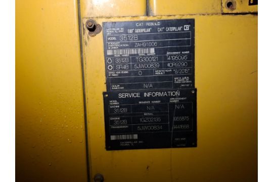
Real-unit nameplate

Kohler KG2204/KG2204T engine engine nameplate / data tag

Nameplate from a real Kohler KG2204/KG2204T engine — photo from a surplusrecord.com listing. How to read one →

Engine specifications

Oil capacity4.2 L
Coolant capacity13.2 L
Displacement2.2 L
Cylinders4
AspirationNaturally aspirated (KG2204); Turbocharged (KG2204T)
Rated speed1800 rpm
Gross power30 kW

Common problems

15
  • Relé de falla común DCB2 DCB2
  • Relé de falla común DCB1 DCB1
    Fix: Llene el sistema de enfriamiento antes de encender el calentador de bloque. Ponga en marcha el motor hasta que este se caliente y llene el radiador para purgar el aire del sistema antes de energizar el calentador de bloque.
  • Battery short circuits.
    Fix: Disconnect or reconnect generator before servicing the equipment. Jewelry should be removed before servicing the equipment. Use tools with insulated handles. Remove the negative (-) lead first when disconnecting the battery. Reconnect the negative (-) lead last when reconnecting the battery. Never connect the negative (-) battery cable to the positive (+) connection terminal of the starter solenoid.
  • Three unsuccessful starting attempts. Over Crank
    Fix: Check the fuel supply, spark plug, and battery. Check for loose connections. Contact an authorized distributor/dealer for service.
  • The generator set is not in Automatic (standby) mode. Remote start and stop commands from a transfer switch or remote switch will be ignored. Not in Auto
    Fix: Press AUTO to place the generator set in Automatic mode, when appropriate.
  • The generator set does not crank.
    Cause: Battery weak or dead, Battery connections reversed or poor, Blown fuse(s)
    Fix: Recharge or replace the battery, Check the connections, Replace the fuse. Contact an authorized Kohler distributor/dealer for service if fuse blows repeatedly
  • The generator set cranks but does not start, starts hard, lacks power, or operates erratically.
    Cause: Air cleaner clogged, Battery weak or dead, Battery connection poor, Spark plug wire connection loose
    Fix: Clean and/or replace the air cleaner, Recharge or replace the battery, Clean and tighten the battery connections, Check the spark plug wires
  • The engine ECM indicates low oil pressure. Oil Pres Low
    Fix: Note: The low oil pressure shutdown does not protect against low oil level. Check the engine oil level regularly as recommended in Section 4. Check for leaks in the lubrication system. Check the oil level and add oil if the level is low. Check the oil pressure switch and wiring.
  • The emergency stop switch has been activated, or there has been an open circuit in the wiring. Emerg Stop
    Fix: Contact an authorized distributor/dealer for service.
  • The ECM reported an Engine Air Temperature/Manifold Absolute Pressure Sensor (TMAP) error. IAT Volt Lo
    Fix: Contact an authorized distributor/dealer for service and provide the fault code.
  • The ECM reported a problem with the coolant temperature sensor reading: 5 = open circuit. CoolntTemp 5
    Fix: Contact an authorized distributor/dealer for service and provide the fault code.
  • The ECM reported a problem with the coolant temperature sensor reading: 4 = low voltage. CoolntTemp 4
    Fix: Contact an authorized distributor/dealer for service and provide the fault code.
  • The ECM reported a problem with the coolant temperature sensor reading: 3 = high voltage. CoolntTemp 3
    Fix: Contact an authorized distributor/dealer for service and provide the fault code.
  • Remote stop command received from a remote switch, ATS, or OnCuer Plus.
    Fix: Check the remote switch position
  • Overspeed shutdown.
    Fix: Reset the controller. If the overspeed fault occurs again, contact an authorized Kohler distributor/dealer

Compiled from service & troubleshooting documentation across every generator set that uses the Kohler KG2204/KG2204T.

Maintenance schedule

ItemSpecCapacityPart #Interval
Air filter400 hr
Oil filter120 hr
BatteryCheck charge, electrolyte level, cracks/corrosion; clean cables120 hr
BeltDeflection new 5-7 mm; used 7-8 mm at 98 N (22 lb.) applied pressure120 hr
Coolant50% ethylene glycol long-life coolant / 50% clean, softened water13.2 L (3.5 gal.) (13.7 L / 3.6 gal. with block heater)500 hr
OilSAE 5W-30 (cold) or 10W-30 (hot), API service class SJ or higher, multi-viscosity synthetic4.2 L120 hr
Spark plugGap 0.7-0.8 mm (0.028-0.031 in.); torque 25 Nm (18.4 ft. lb.)GM100158500 hr Amazon eBay $49.00

Pooled from every document that names this exact engine — confirm the interval and part number against your unit's serial number.

Service intervals

40
ItemActionHoursMonthsNotes
Battery connectionsCheck10 hrWeekly or every 10 hours; tightness and corrosion
Coolant system hoses and clampsCheck10 hrWeekly or every 10 hours
Fuel system leaksCheck10 hrWeekly or every 10 hours; hissing sounds, gas odor
Fuel system leaks, hissing sounds, gas odorCheck10 hrWeekly or every 10 hours of operation
Oil and coolant leaksCheck10 hrWeekly or every 10 hours of operation
Wiring and electrical connectionsCheck10 hrWeekly or every 10 hours of operation; repair or replace loose/damaged components
Air cleaner elementClean20 hr3 moReplace at 3 years or 400 hours
Air filterClean20 hr3 moQuarterly or every 20 hours; refer to equipment Operation Manual
All fastenersCheck20 hr3 moQuarterly or every 20 hours
Battery voltageCheck20 hr3 moQuarterly or every 20 hours; charge or replace as needed
Bolts and nuts for tightnessCheck20 hr3 moQuarterly or 20 hours
FastenersCheck20 hrQuarterly or every 20 hours of operation
BatteryInspect120 hr12 moYearly or every 120 hours; check for cracks, damaged electrodes, corrosion
Battery (cracks, electrodes, corrosion)Inspect120 hrYearly or every 120 hours of operation
Battery cablesClean120 hr12 mo
Battery chargeCheck120 hr12 mo
Battery fluid levelCheck120 hr12 mo
Battery for cracks and corrosionCheck120 hr12 mo
Belts and belt tensionCheck120 hr12 moSee engine O/M
Drive belt tensionAdjust120 hr12 moYearly or every 120 hours; adjust or replace if necessary
Drive-belt tensionAdjust120 hrYearly or every 120 hours of operation; replace if necessary
Engine oil and filterChange120 hr12 mo
Engine oil and oil filterChange120 hr
Engine oil and oil filterReplace120 hr12 moYearly or every 120 hours of operation
Fuel regulator pressureCheck120 hr12 mo
Radiator exteriorCheck120 hr12 mo
Brushes and collector ringOther300 hr12 moAuthorized distributor/dealer only
Air filter element(s)Change400 hr36 mo3 years or every 400 hours; see equipment Operation Manual
Air filter element(s)Replace400 hr36 mo3 years or every 400 hours of operation
Air induction for leaksCheck500 hr36 mo
Engine coolantChange500 hr36 moLong-life coolant: 5000 hours or 5 years
Hoses, conditionCheck500 hr36 moReplace as necessary
Intake manifold for vacuum leaksCheck500 hr36 mo
Secondary ignition coil wiresCheck500 hr36 moReplace as necessary
Spark plug condition and electrode gapCheck500 hr36 mo3 years or every 500 hours of operation; adjust gap or replace if discolored/damaged
Spark plug condition and gapCheck500 hr36 moAdjust gap if necessary; replace if discolored or damaged
Spark plug wires for cuts, abrasions, or hardeningCheck500 hr36 moReplace as necessary
Spark plugsChange500 hr36 mo
Exhaust manifold for leaksCheck2000 hr60 moReplace as necessary
Exhaust piping for leaksCheck2000 hr60 mo

Extracted from the manufacturer documentation linked to this model. Values are copied as printed; confirm against your unit's manual and serial number.

Service specifications

60
TypeItemValueUnitCondition
ClearanceDrive belt deflection - new5–7mm (0.20–0.28 in.)98 N (22 lb.) applied test pressure
ClearanceDrive belt deflection - new belt5-7mm (0.20-0.28 in.)Applied test pressure 98 N (22 lb.) at belt midpoint
ClearanceDrive belt deflection - used7–8mm (0.28–0.31 in.)98 N (22 lb.) applied test pressure
ClearanceDrive belt deflection - used belt7-8mm (0.28-0.31 in.)Applied test pressure 98 N (22 lb.) at belt midpoint
ClearanceDrive-Belt Tension Deflection - New5–7mm (0.20–0.28 in.)Applied Test Pressure 98 N (22 lb.)
ClearanceDrive-Belt Tension Deflection - Used7–8mm (0.28–0.31 in.)Applied Test Pressure 98 N (22 lb.)
GapSpark plug gap0.51mm (0.02 in.)
GapSpark plug gap0.7--0.8mm (0.028--0.030 in.)
GapSpark plug gap0.7-0.8mm (0.028-0.030 in.)
GapSpark plug gap0.76mm (0.03 in.)
GapSpark plug gap0.7–0.8mm (0.028–0.030 in.)
GapSpark plug gap0.8--0.9mm (0.03--0.04 in.)
GapSpark plug gap0.89mm (0.035 in.)
GapSpark plug gap0.9--1.0mm (0.036--0.04 in.)
GapSpark plug gap0.9-1.0mm (0.036-0.040 in.)
GapSpark plug gap0.9–1.0mm (0.036–0.040 in.)
GapSpark plug gap - KG22040.9-1.0mm (0.036-0.040 in.)
GapSpark plug gap - KG2204T0.7-0.8mm (0.028-0.031 in.)
OtherBattery wrap length1067 (42)mm (in.)
OtherBattery wrap length864 (34)mm (in.)
OtherCompression ratio10.5:1
OtherElectric Starter1.2kW, speed reduction type
OtherHeater wrap rating50Watts
OtherHeater wrap rating65Watts
OtherPlug cord length75 (3)mm (in.)
OtherPower cord length1677 (66)mm (in.)
OtherPower cord length1830 (72)mm (in.)
OtherPower cord length483 (19)mm (in.)
PressureFuel supply test pressure6-8ounces per square inch (10-14 inches water column)leak test with soap and water solution
PressureLPG maximum fuel pressure, engine OFF no load2.74kPa (11.0 in. H2O)
PressureLPG minimum fuel pressure, engine ON full load1.7kPa (7.0 in. H2O)
PressureNG maximum fuel pressure, engine OFF no load2.74kPa (11.0 in. H2O)
PressureNG minimum fuel pressure, engine ON full load1.7kPa (7.0 in. H2O)
PressureRadiator pressure cap rating97kPa (14 psi)
SpeedRated engine speed1800rpm
SpeedRated speed1800rpm
TemperatureThermostat off temperature27C (80 F)
TemperatureThermostat on temperature16C (60 F)
TemperatureThermostat valve fully open temperature88°C (190°F)
TemperatureThermostat valve lift fully open88°C (190°F)
TemperatureThermostat valve open76°C (169°F)
TemperatureThermostat valve open temperature76°C (169°F)
TorqueOil Filter Tightening25N•m (18.4 ft.lbs.) - additional 3/4 turn
TorqueOil Pan Drain Plug Torque20–25N•m (14.8–18.4 ft.lb.)
TorqueOil cooler adapter nut40Nm (29.5 ft. lb.)
TorqueOil cooler adapter nut torque40Nm (29.5 ft. lb.)
TorqueOil filter25Nm (18.4 ft. lb.)tighten additional 3/4 turn after hand-tight
TorqueOil filter torque25Nm (18.4 ft. lb.)
TorqueOil pan drain plug20–25Nm (14.8–18.4 ft. lb.)
TorqueOil pan drain plug torque20-25Nm (14.8-18.4 ft. lb.)
TorqueSpark Plugs - KG2204 (standard torque table)18N•m (13.3 ft.lb.)
TorqueSpark Plugs - KG2204T (standard torque table)25N•m (18.4 ft.lb.)
TorqueSpark plug18Nm (13.3 ft. lb.)
TorqueSpark plug25Nm (18.4 ft. lb.)
TorqueSpark plug torque15Nm (11 ft. lb.)
TorqueSpark plug torque18Nm (13.3 ft. lb.)
TorqueSpark plug torque24.4--29.8Nm (18--22 ft. lb.)
TorqueSpark plug torque25Nm (18 ft. lb.)
TorqueSpark plug torque - KG220418Nm (13.3 ft. lb.)
TorqueSpark plug torque - KG2204T25Nm (18.4 ft. lb.)

Extracted from the manufacturer documentation linked to this model. Values are copied as printed; confirm against your unit's manual and serial number.

Recommended fluids

FluidGradeStandardAmbientCapacityNotes
Coolant50% long life coolant / 50% clean, softened waterabove -37°COverheating protection to 149°C (300°F); do not mix long-life and conventional coolants or different colors of long-life coolant
Coolant50% ethylene glycol-based long-life coolant / 50% clean, softened water37°C to 149°C12.4 L (13.1 gal.)Freezing protection to -37C (-34F), overheating protection to 149C (300F); do not mix long-life and conventional coolants, no alcohol/methanol antifreeze
Engine oil5W-30 (cold), 10W-30 (hot), API service class SJ or higherAPI Starburst certification mark for gasoline engines4.2 L (4.4 qt.)CC or CD classification oils (even labeled HEAVY DUTY or For Natural Gas Engines) are not acceptable
Engine oilSAE 5W-30 (cold environments) / SAE 10W-30 (hot environments), API service class SJ or higherAPI Starburst certification mark for gasoline engines4.2 LDo not mix different brands or types of oil; do not use straight-weight industrial/CC/CD oils
Engine oilSAE 5W-30 (cold environments); 10W-30 (hot environments, never below 0C/32F)API Starburst certification, service class SJ or higher (gasoline engines)4.2 L (4.4 qt.)CC/CD classification oils not acceptable
Engine oilSAE 5W-30, API service class SJ or higher (colder environments); SAE 10W-30, API SJ or higher (hot environments)API SJbelow 0°C4.2 L (4.4 qt.)Do not mix different brands or types of oil; multi-viscosity synthetic oils recommended
GreaseHigh-quality lithium-based automotive greaseFor alternator and starter bearings
Greasehigh-quality lithium-based automotive greaseFor alternator and starter bearings

Extracted from the manufacturer documentation linked to this model. Values are copied as printed; confirm against your unit's manual and serial number.

Fault codes

44
CodeNameMeaningSeverityAction
AC Sens LossAC Sensing LostAC sensing lost in Auto mode; warning after 1 sec if no output after crank disconnect, shutdown after 3 sec if voltage was present then lostWarningContact an authorized distributor/dealer for service
ATS ComErrorATS Communication ErrorRXT interface connection is lostWarningCheck communication wiring between transfer switch interface board and generator set
ATS PhaseRotATS Phase Rotation MismatchTransfer switch phase rotation does not match; ATS will not transferWarningCorrect the ATS connection per installation manual, wiring diagrams, and labels
Accy PwrOverAccessory Power OverloadOver current fault (short circuit) on the accessory controller power outputWarningContact an authorized distributor/dealer for service
Aux InputAuxiliary InputAn optional customer-connected input is closed (digital input from optional PIM)ShutdownCheck customer-supplied equipment
Battery CrLoCritically Low Battery VoltageBattery voltage falls below 11V for more than 10 seconds; inhibited during crankWarningCheck battery rating/condition and charger operation; charge or replace battery
Battery HighHigh Battery VoltageBattery voltage rises above 133% (16V) of the battery voltage setting for more than 10 secondsWarningCheck battery rating/condition and charger operation
Battery LowLow Battery VoltageBattery voltage falls below the battery voltage setting (typically 12.5V) for more than 90 seconds when engine is not runningWarningCheck battery rating/condition and charger operation; charge or replace battery
Chk DateTimeVerify Date Time SettingThe time and date have not been set on the generator controllerWarningEnter the date and time using the RDC2 controller
CoolTemp VhiEct Higher Than Expected 2Coolant temperature is extremely highShutdownCheck coolant level; check radiator/fans for obstruction; contact dealer with fault code
CoolTempHighEct Higher Than Expected 1Coolant temperature is too highWarningCheck coolant level; check radiator/fans for obstruction; contact dealer with fault code
Coolant Lvl LowLow Coolant Level ShutdownThe coolant level switch input has been activatedShutdownCheck coolant level; check radiator hoses for leaks; contact dealer
CoolntTemp 0Coolant Temp 0 ShutdownECM reported coolant temperature sensor problem: 0 = high temperatureShutdownCheck coolant level and radiator/fans; contact dealer with fault code
CoolntTemp 3Coolant Temp 3 ShutdownECM reported coolant temperature sensor problem: 3 = high voltageShutdownContact an authorized distributor/dealer for service and provide the fault code
CoolntTemp 4Coolant Temp 4 ShutdownECM reported coolant temperature sensor problem: 4 = low voltageShutdownContact an authorized distributor/dealer for service and provide the fault code
CoolntTemp 5Coolant Temp 5 ShutdownECM reported coolant temperature sensor problem: 5 = open circuitShutdownContact an authorized distributor/dealer for service and provide the fault code
Crank LostCrank Signal LostCrankshaft Position Sensor (CPS) timeout error occurredWarningContact an authorized distributor/dealer for service and provide the fault code
ECM warningsECM warnings (any warning with ECM in the fault name)Group of faults that originate from the engine ECM and contain ECM in the fault nameWarningContact an authorized distributor/dealer for service and provide the fault code
Emerg StopEmergency Stop ShutdownThe emergency stop switch has been activated, or there has been an open circuit in the wiringShutdownContact an authorized distributor/dealer for service
Eng Speed HighHigh Engine SpeedEngine speed exceeds 115% of normal running speed for more than 0.3 secondsShutdownContact an authorized distributor/dealer for service
Eng Speed LowLow Engine SpeedEngine speed drops below 85% of normal running speed for more than 3 secondsShutdownReduce the load; contact an authorized distributor/dealer for service
Exer Not SchATS Exercise Not ScheduledNo exercise has been scheduled on the RDC2 controllerWarningSet the exerciser per Section 2.5
Frequency HighHigh FrequencyGoverned frequency exceeds 110% of system frequency setpoint for more than 10 seconds (10 sec inhibit after start)ShutdownContact an authorized distributor/dealer for service
Frequency LowLow FrequencyGoverned frequency falls below 90% of system frequency setting for more than 10 seconds, or 1 Hz below setting for more than 60 secondsShutdownReduce the load and restart; contact dealer
Genset S/N UnavalUnavailable Genset Serial NumberGenerator set serial number is unavailableWarningContact an authorized distributor/dealer for service
Ground FaultGround Fault WarningThe digital input for Ground Fault Warning is active (low); PIM requiredWarningCheck customer equipment connected to the PIM
IAT High 1Iat Higher Than Expected 1Engine manifold air temperature is too highWarningContact an authorized distributor/dealer for service and provide the fault code
IAT Volt LoIat Low VoltageECM reported an Engine Air Temperature/Manifold Absolute Pressure Sensor (TMAP) errorWarningContact an authorized distributor/dealer for service and provide the fault code
Lo Crank VltLow Cranking VoltageBattery voltage falls below 60% of system battery voltage for more than 6 seconds while the starter is engagedWarningCharge or replace the battery
Locked RotorLocked RotorNo engine rotation is sensed during cranking; shuts down 3 seconds after fault detectedShutdownCheck battery, connections, and for obstruction of alternator or engine; contact dealer
MainPwrOverLMain Power OverloadOver current fault on the controller power output (short circuit)ShutdownCheck for shorted run relay; check wiring for short circuits; contact dealer
Maint Req'dMaintenance Required WarningEngine maintenance is dueWarningCheck the maintenance schedule in the operation manual
Not in AutoNot In AutoThe generator set is not in Automatic (standby) mode; remote start/stop commands will be ignoredWarningPress AUTO to place the generator set in Automatic mode
Oil Pres LowLow Oil PressureThe engine ECM indicates low oil pressureShutdownCheck for leaks in the lubrication system; check oil level; check oil pressure switch and wiring
Over CrankOver CrankThree unsuccessful starting attemptsShutdownCheck fuel supply, spark plug, battery, and connections; contact dealer
PrimLoopOpnPrimary Loop OpenIgnition coil 1 voltage is below normal or there is an open circuitWarningCheck the battery voltage; contact dealer with fault code
PrimLoopShtPrimary Loop ShortedIgnition coil 1 voltage is abnormalWarningCheck the battery voltage; contact dealer with fault code
Spd Sens FltSpeed Sensor FaultEngine speed sensor has failed or engine stalled; ECM no longer reporting valid speedShutdownContact an authorized distributor/dealer for service
Volts L1-L2 HighHigh Generator Voltage L1-L2Output voltage exceeds 120% of system nominal voltage for more than 2 secondsShutdownContact an authorized distributor/dealer for service
Volts L1-L2 LowLow Generator Voltage L1-L2Output voltage falls below 80% of nominal system voltage for more than 10 secondsShutdownReduce the load and restart; contact dealer
Volts L2-L3 HighHigh Generator Voltage L2-L3Output voltage exceeds 120% of system nominal voltage for more than 2 secondsShutdownContact an authorized distributor/dealer for service
Volts L2-L3 LowLow Generator Voltage L2-L3Output voltage falls below 80% of nominal system voltage for more than 10 secondsShutdownReduce the load and restart; contact dealer
Volts L3-L1 HighHigh Generator Voltage L3-L1Output voltage exceeds 120% of system nominal voltage for more than 2 secondsShutdownContact an authorized distributor/dealer for service
Volts L3-L1 LowLow Generator Voltage L3-L1Output voltage falls below 80% of nominal system voltage for more than 10 secondsShutdownReduce the load and restart; contact dealer

Extracted from the manufacturer documentation linked to this model. Values are copied as printed; confirm against your unit's manual and serial number.

Procedures

12
12-Lead Generator Reconnection Procedure adjustment

⚠ Verify that voltage ratings of transfer switch, line breakers, and accessories match the selected line voltage

Tools: digital multimeter, voltmeter

  1. Press the OFF button on the RDC2 controller
  2. Disconnect engine starting battery, negative lead first
  3. Disconnect utility power to the generator set
  4. Select desired voltage connection and connect leads according to the diagram
  5. Reconnect engine starting battery, negative lead last
  6. Enter the RDC2 Genset System menu and check/change system voltage, frequency, phase settings
  7. Connect a digital multimeter (DVM) to the generator set output
  8. Press RUN to start the generator set
  9. Use a voltmeter to check output voltage and calibrate if necessary
  10. Press OFF to stop the generator set
  11. Reconnect utility power to the generator set
  12. Press AUTO to place the generator set in automatic mode
Fuel Conversion: Reset Regulator for NG adjustment
  1. Push up on the adjusting cap and rotate counterclockwise, release upward pressure, and lock into place
  2. Disconnect wire N20 and wire 45
Fuel Conversion: Set Regulator for LPG adjustment

⚠ Do not adjust the IEPR or the air/fuel mixer

  1. Push the adjusting cap to its upper stop and rotate clockwise, release upward pressure, and lock into place
  2. For LPG fuel only, use the quick-connect adapters to connect wire N20 from the fuel pressure regulator to wire 45 from the ECM wiring harness
NG to LPG Conversion adjustment

⚠ Accidental starting can cause severe injury or death

⚠ Risk of fire near fuels or fuel system

⚠ Explosive fuel vapors can cause fires and severe burns

  1. Disconnect battery cables, negative lead first, before working on engine
  2. Push the regulator adjusting cap to its upper stop and rotate clockwise for LPG, release and lock into place
  3. For LPG only, connect wire N20 from the regulator to wire 45 from the ECM harness using quick-connect adapters
  4. To reset for NG, push up the adjusting cap and rotate counterclockwise, release and lock
  5. Disconnect wire N20 and wire 45 to reset for NG
RDC2 Voltage Calibration Using SiteTech adjustment

Tools: digital voltmeter, personal computer, SiteTech software

  1. Connect PC to controller via USB
  2. With generator off, connect multimeter across L1/L2 (AC volts)
  3. Start generator set
  4. Compare voltmeter reading to controller display
  5. Calculate new Genset Calibration Factor Voltage using (Vmeter / Vcontrol) x Fold = Fnew
  6. Enter new value into SiteTech and click Apply Changes
  7. Verify voltmeter matches controller display
  8. Repeat for L2-L3 and L3-L1 if three-phase
  9. Press OFF to stop generator set
RDC2 Voltage Calibration Using the Controller Keypad adjustment

Tools: digital voltmeter

  1. With generator off, connect digital multimeter across L1 and L2, set to AC volts
  2. Start generator set with RUN button
  3. Navigate to Generator Metering menu, press Select; Volts L1-L2 displayed
  4. Press Select; voltage number flashes
  5. Use up/down arrows to match voltmeter reading
  6. Press Select to confirm
  7. Step to Return screen
  8. Press OFF to stop generator set
VSC Current (Load) Calibration Using the Controller Keypad adjustment

Tools: clamp-on DC current probe or DC current meter

  1. Connect DC current probe/clamp meter to measure generator current
  2. Start generator with RUN button
  3. Adjust system voltage to obtain rated current output with battery bank attached (or use load bank)
  4. Trip output breaker
  5. Navigate to Generator Metering menu, select Generator Load
  6. Press and hold Select for No-Load Calibration; verify breaker open, confirm Yes
  7. Close output breaker; verify rated output current, confirm Yes
  8. Verify displayed load is correct; recalibrate if necessary
  9. Press OFF to stop generator set
Voltage Calibration Using RDC2 Controller Keypad and Menus adjustment

Tools: digital multimeter

  1. With the generator set off, connect a digital multimeter to measure output voltage across L1 and L2
  2. Start the generator set by pressing RUN
  3. Navigate to the Generator Metering menu
  4. Press Select to display Volts L1-L2 and compare to the voltmeter reading
  5. If incorrect, press Select, use up/down arrows to adjust voltage to match the voltmeter, press Select to save
  6. Wait 30-60 seconds for the reading to stabilize
  7. For three-phase models, repeat for L2-L3 and L3-L1
  8. Step to Return and exit the Generator Metering menu
  9. Press OFF to stop the generator set
Resetting the Controller after a Fault Shutdown diagnostic

⚠ Always identify and correct the cause of a fault shutdown before resetting

  1. Press the Select button to go to the Overview menu
  2. Press Select again to display the active fault
  3. Press Select; Confirm Clear Fault: NO is displayed
  4. Press the Up arrow button; Confirm Clear Fault: YES is displayed
  5. Press Select to enter YES and clear the fault
  6. Press Select to return to the Overview menu
  7. Press AUTO to put the generator set into automatic mode
Engine Starting Battery Installation installation

⚠ Sulfuric acid in batteries can cause severe injury or death

  1. Ensure the starting battery is fully charged before placing in service
  2. Clean the battery posts and/or adapters if necessary
  3. Install battery post adapters if needed
  4. Place the battery on the battery rack on the skid
  5. Connect the red battery cable to the positive (+) battery terminal
  6. Connect the black battery cable to the negative (-) battery terminal
  7. Place the boots over the battery terminals
Fill the Cooling System installation

⚠ Hot coolant and steam can cause severe injury or death

⚠ Do not add coolant to a hot engine

  1. Close the radiator's coolant drain valve and tighten the hose clamps
  2. Fill the radiator with the recommended coolant mixture of 50% ethylene glycol-based long-life coolant and 50% clean, softened water
  3. Check the oil level before operating the engine
  4. Operate the engine with the radiator's pressure cap removed until the thermostat opens and the upper hose becomes hot
  5. Stop the engine and allow it to cool
  6. Add coolant to the radiator to just below the overflow tube on the filler neck
  7. Replace the radiator's pressure cap
  8. Maintain the coolant level in the overflow bottle between the Hot and Cold markings
Generator Installation installation

⚠ Minimum clearances required per NFPA 37

⚠ Local codes may require greater distances

  1. Exhaust must be aimed away from or parallel to the structure.
  2. Do not direct exhaust at play areas, patios, or congregation areas.
  3. Place nearest window, vent, door at least 5 feet from exhaust end.
  4. Install minimum 18 inches from structure per NFPA 37 (verify local codes).
  5. Keep windows and doors on adjacent walls closed.
  6. Place furnace and similar intakes at least 10 feet from exhaust.
  7. Install 4-inch thick concrete pad extending 6 inches beyond genset.
  8. Remove plants, shrubs, combustibles from minimum 8-foot clearance area.
  9. Position sensitive plants and furniture at least 8 feet from exhaust.

Extracted from the manufacturer documentation linked to this model. Values are copied as printed; confirm against your unit's manual and serial number.

Voltage reconnection

VoltagePhaseConnectionLeadsNotes
LPG conversion (set regulator for LPG)Connect wire N20 from fuel pressure regulator to wire 45 from ECM wiring harness using quick-connect adaptersReverse (disconnect wire N20 and wire 45) to reset for NG
Three-phase (12-lead)Reconnectable to voltages/phases per generator set specification sheet12-leadSee Figure 3-2, 24RCL and 30RCLH
100/2001Single
100/2003Delta
110/2201Single
110/2203Delta
115/2301Single
1201SingleGenset System Voltage/Frequency/Phase table for controller setup
120/20834D5.012, ReconnectableThree-phase
120/20834D8.312, ReconnectableThree-phase
120/2083Wye
120/24014E5.04Single-phase
120/24014E8.34Single-phase
120/2401Single
120/2403Delta
120/240 VSingle-phase (four-lead)Factory connection, not reconnectable4-lead60 Hz; see Figure 3-1
127/22034D5.012, ReconnectableThree-phase
127/2203Wye
2201Single
220/3803Wye
2301Single
230/4003Wye
2401Single
240/4163Wye
277/4803Wye

Extracted from the manufacturer documentation linked to this model. Values are copied as printed; confirm against your unit's manual and serial number.

Parts cataloged across the Kohler KG2204 family

18
Part #DescriptionCategory
24RCLKOHLER 24RCL generatorother_service
256984Battery, 12 volt wet-charged, BCI group size 24, 650 CCA at -18 C, 120 min. reserve capacityother_service
30RCLKOHLER 30RCL generatorother_service
GM100209Maintenance Service Kitother_service
GM104032-S1Service kit with two L-shaped metal shields and U-channel edging for shielding the RDC2 controller from EMI interference.other_service
GM104703-KP1Battery heater kit, 120 Volts, heater wrap rating 50 Watts, battery wrap length 864 mm (34 in.), power cord length 483 mm (19 in.), plug cord length 75 mm (3 in.)other_service
GM62348-SKP1-QSMaintenance Kitother_service
GM83718-SKP1-QSMaintenance Kitother_service
GM86771-SKP1-QSMaintenance Kitother_service
GM88832Flywheel adapterother_service
GM89020-KP1Battery kit, wet-charged, contains 1 battery, BCI group size 24, 650 CCA, 120 min. reserve capacity (loose kit only)other_service
GM89979-SKP1-QSMaintenance Kitother_service
GM90230Figure 1-23 Coolant Fill (24RCL shown)other_service
GM92075Figure 1-24 Coolant Fill (30RCL and 38RCLB shown)other_service
GM93396Maintenance Service Kitother_service
GM93396-SKP1-QSMaintenance Kitother_service
GM100158Spark Plug (use only genuine Kohler service parts)spark_plug
GM92785Spark plug, screw thread M14 x 1.25 (KG2204 only)spark_plug

Parts cataloged across all variants of this engine family — verify the exact part fits your specific variant and serial number before ordering.

Common questions

What is the oil capacity of the Kohler KG2204/KG2204T?

The Kohler KG2204/KG2204T engine has an oil capacity of 4.2 liters.

What is the displacement of the Kohler KG2204/KG2204T?

The Kohler KG2204/KG2204T has a displacement of 2.2 liters with 4 cylinders.

Which generators use the Kohler KG2204/KG2204T engine?

The Kohler KG2204/KG2204T powers 6 generator set(s), including Kohler 24RCL, Kohler 25CCL, Kohler 30CCL, Kohler 30RCL, Kohler 36CCL.

How often should you change the oil in the Kohler KG2204/KG2204T?

The Kohler KG2204/KG2204T oil change interval is every 120 hours.

What is a common problem with the Kohler KG2204/KG2204T engine?

A commonly reported issue on generators using the Kohler KG2204/KG2204T is: Relé de falla común DCB2.